Warning this should only be done via a certified electrician. I take no responsible for any harm you experience by executing my instruction
Neon sign transformers (NSTs) are the preferred power supplies. Recently manufactured NSTs include a GFCI (ground fault circuit interrupter) also known as a GFI (ground fault interrupter) circuit that will “trip” or automatically shut off a NST when it detects an unusual current in the output of the NST. Unfortunately Tesla coils produce current spikes that frequently cause the GFCI circuit to shut off the NST, making NSTs with GFCI unreliable in a Tesla coil. NSTs with a GFCI circuit will usually have a GFCI reset button somewhere on the case or possibly under the top cover. It may be possible to rewire and bypass the GFCI circuit in the NST, although it may be a very difficult process depending on the complexity and location of the GFCI wiring. Newer, small NSTs are actually solid state power supplies that are unsuitable for Tesla coils. I strongly recommend using an older NST to power your Tesla coil. A good NST should be very heavy and only contain a primary winding, secondary winding and metal core. The output frequency should be the same as the input frequency (50 or 60 Hz). My example is the F.A.R.T. 10 KV and 100 mA Neon sign transformer, which allows to remove the GFCI connection.
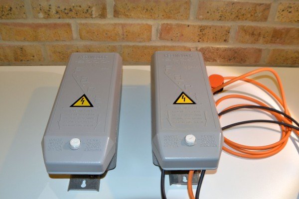
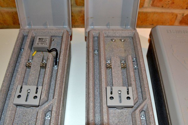
Below you see on the left side a new F.A.R.T. Neon Transformer and on a the right side the one I have converted for use with my high voltage experiments.
What do I need?
1. A NST which is not solid state. It has to be heavy. The F.A.R.T. weights 17 KG
2. Screwdriver, Hot glue gun or better epoxid
3. Power cable for the correct power rating. For a 1000 Watt NST 1.0 mm copper cable is fine
4.GTO15, High voltage cable. That is no cable you can buy around the corner from B&Q or Radio shack. I have some good sources and bought a couple of 100 feet for a good price. Details can be found via TESLA Stuff. Link is under Tutorial.
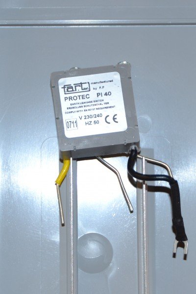
1.Open the cover and remove the GFI
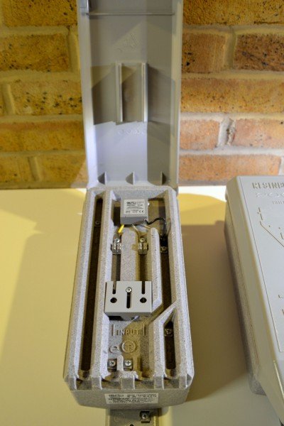
The lid or cover contains two small and thin metal stripes. They connect the mains power to the transformer. In open state it is disconnected. On top you see the little electronic box with the leads for terminal connections.
2. NST without GFI
I have removed the GFI as you can see on the right side . The left one is the new original one from the supplier
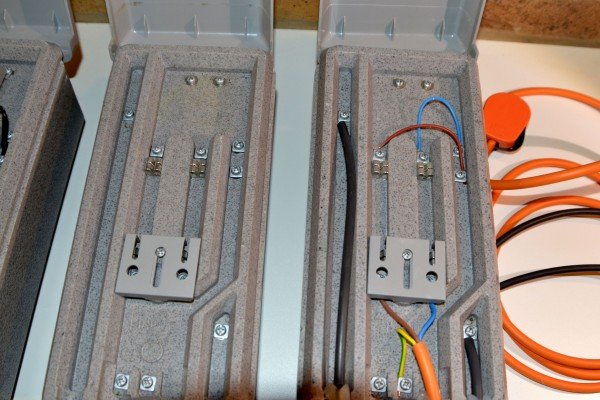
3. Add the new wiring without the GFI
The blank connected on in the middle and the completed one on the right side.
Right and left on the NST are the HV GTO15 cable terminals.
Earth for the mains is marked here in yellow green.
When you connect the mains in the bottom section make sure that you continue on top with the same polarity. In my example, life on the left and neutral on the right. They need to be correct connect on the vary right side. Brown for life and blue for neutral. Connected wrong will trip the fuse. The transformer is balanced with neutral in
the middle of the transformer of the secondary winding. This is also connected to the ground to the base plate of the NST