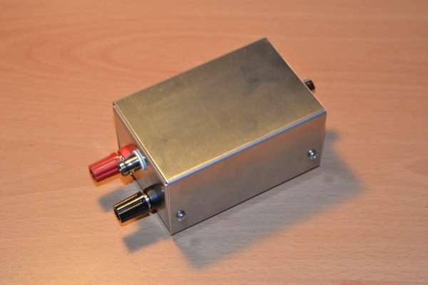
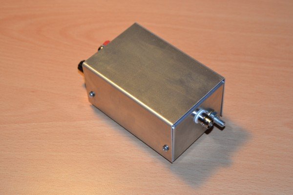
Building an RF transmitter driver and amplifier circuit – Part 1
Driver circuit to drive gate of Power RF MOSFET or Standalone RF Transmitter
This tutorial is based on the obsolete RF driver not reproduce able anymore, except for the amplifier stage with the same Package 275 style
On the search for powerful electronic RF Transmitter I came across a Driver from IXYS> They produce production broadcast systems. This chip with the DE375 in dual mode can dissipate up to 10 KW of RF power. That is serious stuff and not available from Radio Shack. It is also affordable. A vacuum RF amplifier is expensive and difficult to build. If you look for vintage equipment go to Nebraska Surplus. That is where I got mine from. E. G. 1B22 and air capacitors as well as RF meter.
What do I need?
1. The IXYS IC Chip, DEIC420 ( is Obsolete, replacement recommondation is IXRFD630)
2. A strip board cut to size for the housing, or better the original evaluation circuit board
3. Metal housing to shield RF interference
4. Isolated 50 Ohm BNC plug
5. 4mm Cinch female housing connector
6. 2 X 0.25 OHM, 2 watt resistor
7. 2 x 470 PF Capacitor, 35-50 Volt
8. 4 X 4.7 uF Capacitor, 35-50 Volt
9. 4 X 1 nF Capacitor, 35-50 Volt
10. 4 X 0.47 uF Capacitor, 35-50 Volt
11. 10 Ohm Resistor
12. 50 Ohm Resistor
13. Isolating Capacitor to output, variable depending on used frequency, smaller then1 nF.
Not included in this part.
14. 4X3mm nuts and bolts to fix the circuit board
15. Thermal paste for heat dissipation of the IC Chip
16. Ferrite frequency suppressor on the input side to shunt higher harmonics.
We might add a 5 element low deep pass filter to increase gain to our reference frequency. Not for compliance purpose as stated.
1.Circuit drawing
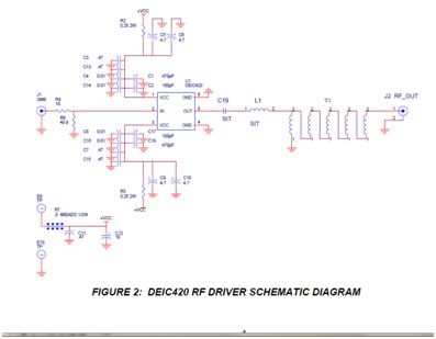
We do not use the exact layout. We ignore the output optimisation for a resonant frequency and also the 50 Ohm output loading coil. We go straight to the RF Power MOSFET later in part 2 of the RF power amplifier building instructions.
2. Part list
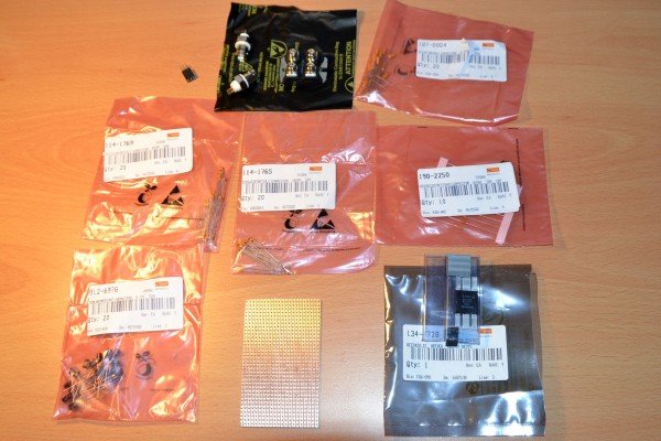
I provided a couple of pictures of the components we use below.
The power RF MOSFET will be used in part 2
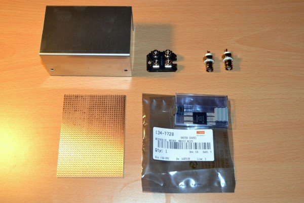
Components bought from Farnell. Some of the components are special and only from them available. The 0.25 Ohm, Ohmite resistor with 1% precision for example. I got the 5 Watt, 2 watt is efficient to decouple from the power supply
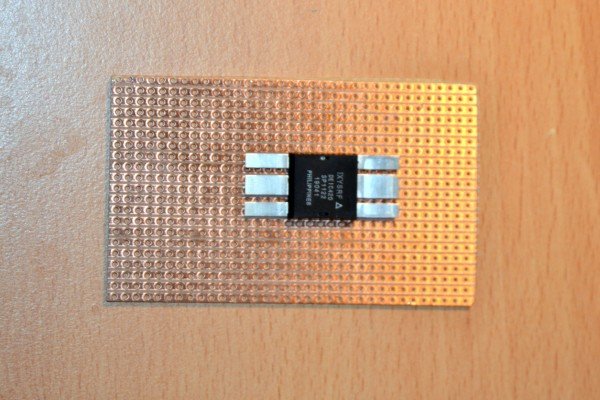
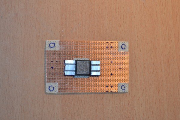
Stripboard and the DEIC420 chip. We have to solder it on this board
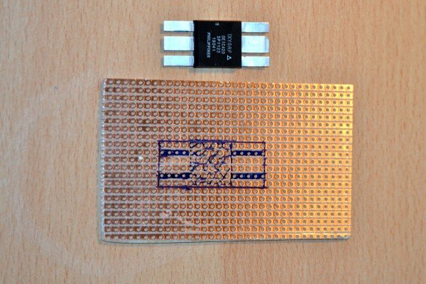
We mark on the board the pin layout. Wear static shielding when handle this chip. The copper below the blue markings has to be removed for the chip.
Remove the copper with either a rotary tool or use a copper strip scraper.
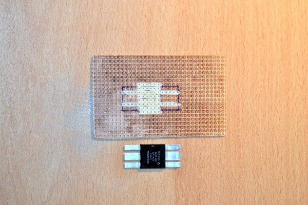
I remove at the corner a square and mark the section for drilling a hole. We need to mount it in the case and also to solder the chip with heat sink part outside. Depending on your usage you might need a big heat sink or even water cooling.
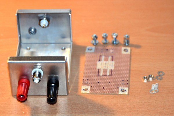
Ready to solder strip board and the case with BNC connectors and power plugs. There is a earth connector for ground on the opposite side.
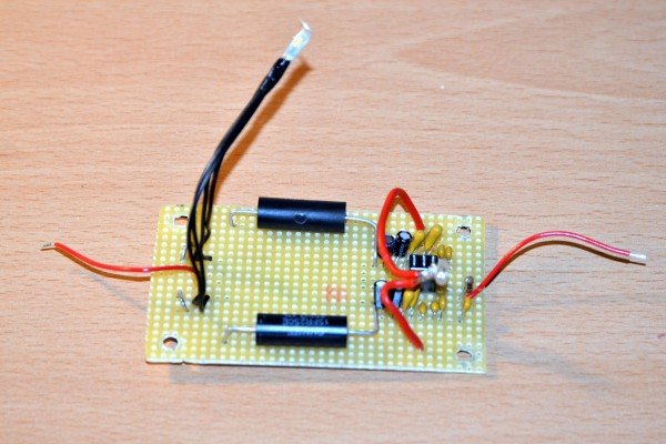
Complete soldered. Symmetry is very important. Also the capacitor needs to have some Tantalum in it. I use 4, 2 for each side. Unfortunately I got only get the 5 watt 0.25 Ohm resistor, 2 watt is efficient. Its job is to decouple from the power supply.
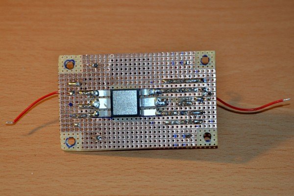
Chip soldered. Not pretty but it works. Make sure you use thermal past on the metal surface. It is not connected to any components of the chip so don’t worry about polarity of the case. Screw it tight to the case but not too much, the strip board bends easily. I achieved a good heat dissipation however the case is not enough for full power dissipation. 150 degree is max. Use a resistor on the Plus polarity of the power supply. Best choice is between 5 and 50 Ohm, iron clad 50-100 watt resistor. No additional cooling then required. I got around 35 watt power uot of it up to 30 volt and had around 40 volt on the LCR circuit with a hand warm case. We use the power amplifier to do that job. Easier to control.
All connected. Heat sink just in case you want to use it. Connect on the side panel. Heat transfer will not be ideal but better than nothing.
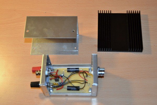
Completely mounted